Fingerpainting
 At the head end of my life I took a painting class but remember very little of it, including the instructor's name, which saddens me. One quirk of his that has always stuck with me is the phrase: “...the physicality of paint!”, which he would frequently urge upon us, because – at the bottom of it all – our still lives with apples or landscapes with pasturing sheep were not ultimately these, these – representations – but bits of oil paint on canvas, which cast shadows and had form and was – well, physical.
At the time I thought it was an indisputable point but one of small moment, unaware of the passionate discussions that the “physicality of paint!” had engendered in prior decades, a founding notion of Action Painting and one that resonated deeply among the New York School, a crowd I think that this worthy ran with in his younger days.
For my part, I was content with the idea of representation. I was cognizant of bits of paper here and there, flecked with green and black pigments, which, to bank tellers, sufficiently represented monetary value to put cash into my checking account, so long as I could get my hands on some of the stuff. So when I saw such bits of paper, the first thought electrifying my mind was “Money!” and not an appreciation of printer's ink.
And yet, small though the point may be, paint is there, sticking to canvas or some other ground, lumpy, with specular highlights and bumps that cast shadows. So this is a G'MIC tutorial celebrating that. It more-or-less re-renders an image as if it was more or less finger-painted, or painted with a broad brush. It's my tribute to this unremembered instructor and his physicality of paint!
All that aside, we have three tasks:
| 1. | conjure out of an arbitrary image a pattern that might produce reasonable looking brush strokes. |
| 2. | render the illusion of paint having been pushed by fingers or brushes along paths defined by these strokes, with concomitant tracings of bristles or fingerprints and ridging of paint pushed to either side. |
| 3. | conjure up a decent enough lighting model so that our output image looks like it could be a photograph of a painting of our input image. |
That's the game. Here's our play:
Physical Paint
The image of a finger or a brush pushing along paint immediately brings to mind tensor fields, produced by diffusiontensors, which directs asymmetrical smoothing kernels in the smooth command to diffuse noise parallel to detected edges – a quite serviceable brush stroke model. So, if you've blown onto this page from somewhere else, your first order of business is to spend some time with “ Do Your Own Diffusion Tensor Field ” and introduce yourself to the anisotropic smoothing bits in G'MIC.The gist of it is this: if we can conjure up out of an image the edges around likely brush strokes, we can harness -diffusiontensors to estimate apt diffusion tensor fields, nominally designed to preserve those edges. If we compose the field with highly elliptic kernels, these can push noise into elongated paths, aping brush or finger strokes.
The following script section sets out to simplify an image with a Gaussian blur, then quantizes the result into a small number of bins. These look like broad areas of constant color, which mark areas over which brush strokes or fingers might traverse. Or might not. We do some morphological simplification of the quantized bins to consolidate tight gradients.
The contour lines delineating brush strokes are also useful in that they locate where ridges form as broad brushes or fingers plow through paint. That, in so many words, is our model of “the physicality of paint!”. Here are the particulars.
gmic -input \
https://commons.wikimedia.org/wiki/File:Ambersweet_oranges.jpg \
-resize2dx[-1] 1024 \
https://commons.wikimedia.org/wiki/File:Ambersweet_oranges.jpg \
-resize2dx[-1] 1024 \
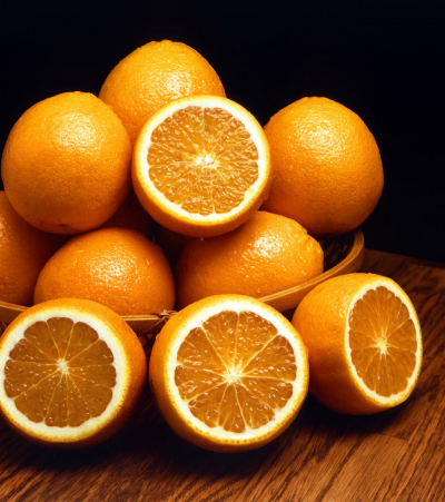 | Image Fetch Some ambersweet oranges, courtesy of the Agricultural Research Service, US Department of Agriculture. We reduce the image to 1024x1155. Such rescaling has a bearing on the outcome, since anisotropic smoothing is scale-dependent. Roughly, apparent finger size increases inversely to image area. Conversely, apparent dexterity improves in direct proportion to image area. In brief, small pictures == fat, clumsy fingers and that's OK if that's what you want. If you want the appearance of smaller fingers/brushes, however, then start with large images. |
lh='{h}' \
+blur[-1] 0.35% \
-quantize[-1] 10 \
+blur[-1] 0.35% \
-quantize[-1] 10 \
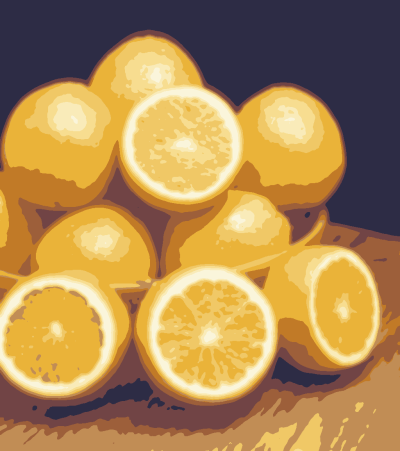 | Find Finger Strokes We add a quantized version of the image to the stack. As the amount of blurring increases, strokes become broader and its resolving power declines. We model fatter fingers or broader brushes. Conversely, less blurring gives rise to more strokes produced by smaller fingers or brushes. We equate a quantized band of uniform color to a brush stroke. With this particular image, we envision a good many circular strokes building up to the highlights of the oranges. |
-gradient_norm. \
-threshold. 15% \
-dilate_circ. 6 \
-thinning. \
-dilate_circ. 3 \
-threshold. 15% \
-dilate_circ. 6 \
-thinning. \
-dilate_circ. 3 \
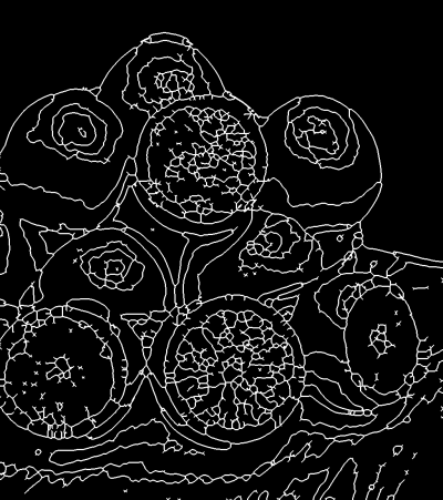 | Generate a 'Finger Stroke Map' Gradient_norm and threshold elucidate the borders between quantized regions, making topographic contours, marking off regions of similar hue and luminance. Roughly, these correspond to finger paint strokes, but the analogy breaks down with tight gradients; fingers are impossibly small. To counter this, a threshold/dilation/thinning cycle merges tightly spaced gradients, with thinning finding the center of these aggregates. A second dilation finalizes the stroked regions and their boundaries. However, the final geometry awaits anisotropic smoothing. To that end, we derive a diffusion tensor field. We invoke diffusiontensors directly so that we may use the resulting diffusion tensor field again and again as well as modify it from time to time. |
+diffusiontensors. 0.1,0.85,0.3,8 \
[-2,-1] \
-resize2dy[-2,-1] '{$lh/2}',5 \
-repeat 3 \
-smooth[-2] [-1],400 \
-done \
-rm. \
-resize. [-3],[-3],[-1],[-1],5,0 \
-reverse[-2,-1] \
[-2,-1] \
-resize2dy[-2,-1] '{$lh/2}',5 \
-repeat 3 \
-smooth[-2] [-1],400 \
-done \
-rm. \
-resize. [-3],[-3],[-1],[-1],5,0 \
-reverse[-2,-1] \
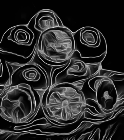 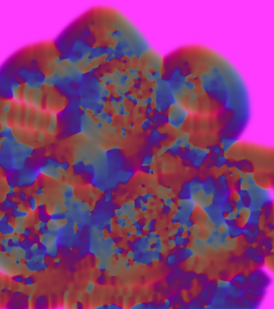 | Smoothing finger strokes We generate a diffusion tensor field and harness it to smooth the finger stroke map. The results establish where paint ridging occurs (light areas), with dark/black areas representing the strokes themselves. The intent of this smoothing step is to reduce many of the sharp turns which arise from the thinned contour map. Fingers or brushes rarely make sharp corners, particularly given the viscosity of real paint. Some areas do not break neatly down into strokes; these are murky gray areas. These turn into smear regions not unlike those made by fingers too fat to capture fine detail (but the attempt is made anyway). We achieve quite violent smoothing through two means. 1. The parameters passed to diffusiontensors are quite extreme, the high anisotropy value and low sharpness value favor highly directional smoothing. 2. We also make reduced-size copies of the tensor field and finger stroke map before invoking the smooth command. The action of the smooth command is scale dependent and is much more pronounced at smaller scales, an effect we deliberately exploit. The diffusion tensor field produced in this step directly or indirectly influences the character of brush strokes throughout the remainder of this script. Used to finally shape the finger stroke map, the same tensor field, modified, largely emulates the bristle brush pattern; in this manner, the orientation of the brush stroke and bristle patterns match because they are both developed from the same underlying tensor field. |
-eigen. \
-split.. c \
-fill_color... 1 \
-fill_color.. 0 \
-append[-3,-2] c \
-eigen2tensor[-2,-1] \
-split.. c \
-fill_color... 1 \
-fill_color.. 0 \
-append[-3,-2] c \
-eigen2tensor[-2,-1] \
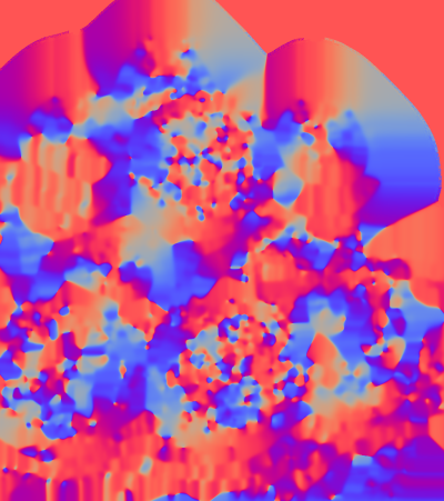 | Modify the diffusion tensor field Readers of Do Your Own Diffusion Tensor Field will recall the breakdown of tensor fields into four gray scale images named EigenOne, EigenTwo, Cosine and Sine. Here, we break out EigenOne and EigenTwo and set them to one and zero across the entire field. These two modifications gives rise to extremely eccentric blurring kernels across the field which are, in turn, steered by the angles encoded in Cosine and Sine. It is through this diffusion tensor field, so modified, that we achive the effects of brush bristles or finger prints. Generally, EigenOne and EigenTwo together control the eccentricity of the diffusion kernels; by setting them to one and zero we'll garner extremely elliptic smoothing kernels and the effect is that of fine bristles. We could make these bristles bigger and coarser by reducing EigenOne somewhat and increasing EigenTwo by a like amount; the two values should still sum to one. Such modifications give rise to less eccentric (i. e. “rounder”) smoothing kernels and the effect will be akin to that of a brush with fewer, fatter bristles. Values of 0.7 for EigenOne and 0.3 for EigenTwo are about as far as one can go in this vein; bristles disappear at these settings and do not reappear until EigenOne is less than 0.3 and EigenTwo greater than 0.7. In this range, however the brush strokes are effectively rotated by 90°, an interesting, if not entirely useful effect. This apparent rotation arises from the nominally “long” axis of the blurring kernel becoming the shorter of the two, while the “short” axis becomes longer. |
98%,98%,1,1 \
-noise. 16,2 \
-abs. \
-resize. [-2],[-2],[-1],[-1],0,0,0.5,0.5,0.5,0.5 \
-to_rgb. \
-mul. [-5] \
-apply_channels[-1] \"-apply_curve 1,0,48,127,220,255,255\",hsv_s \
-noise. 16,2 \
-abs. \
-resize. [-2],[-2],[-1],[-1],0,0,0.5,0.5,0.5,0.5 \
-to_rgb. \
-mul. [-5] \
-apply_channels[-1] \"-apply_curve 1,0,48,127,220,255,255\",hsv_s \
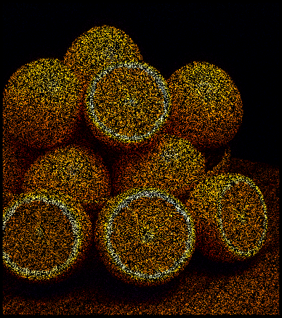 | Emulating Paint We emulate paint using a dull under-color and over saturated, noise-derived over-color, which gives the appearance of brush bristles. The bristles stem from salt-and-pepper impulse noise multiplied by the original image. We could think of the results as brush bristles frozen in time. To unfreeze time, we smooth these bristles with the modified diffusion tensor field from the previous step. Since that field is composed entirely of highly eccentric blurring kernels, these “bristles” will diffuse along lines in accordance to the angles encoded in the Cosine and Sine fields. Since these derive from the “Finger Stoke Map,” the bristles will extrude along paths nicely parallel to the edges in the stroke map. |
+apply_channels[-5] \"-mul 0.6\",hsv_s \
-apply_channels[-1] \"-mul 0.85\",hsv_v \
-apply_channels[-1] \"-mul 0.85\",hsv_v \
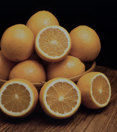 | For the under-color, we desaturate and darken the original image and smooth it with the same diffusion tensor field we applied to the “bristles” image in the previous frame. |
-repeat 3 \
-smooth[-2,-1] [-3],300 \
-done \
-smooth[-2,-1] [-3],300 \
-done \
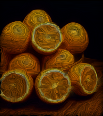 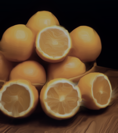 | Over and Under Colors Smoothed, the over and under color images constitute the color component of the finger painting, endowed now with images of bristles (over color) and ground (under-color). We have yet to introduce bumpiness, a sense that this color field is a surface with an irregular height that is lit in some fashion. To that end, we proceed to the lighting model. |
Lighting
Gradients – images which register intensity changes of other images – naturally lend themselves to lighting approximations. We use a pretty unsophisticated model here; its virtue is that it is quick to compute. We light our surfaces by choosing a direction from which we imagine light to be streaming from – the azimuth – and then take the dot product between this unit vector and the elements of a direction field, which we construct from the results of the gradient command.This model is too simple to accommodate the elevation of the light ray, but still it is sufficiently robust to ape incident light rays streaming in at the desired angle and an elevation which could be 45° (we don't press this notion too much). Dotting the azimuth and the direction field results in a gray scale image that ranges from negative to positive one, so long as every vector is normalized first.
Direction fields follow directly from the gradient command, which calculates changes in intensities along width, height and depth axes and produces single channel datasets for each. With append, one may fold such datasets into the channels of a combined object which becomes the direction field; it is a set of vectors which indicates the local magnitude and direction of changing intensity. Technically, the command estimates the first partial derivative of the change of intensity along each principle image axis.
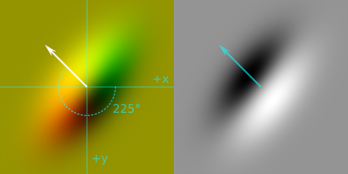 | For surface lighting, we are just interested in the intensity changes along the width and height axes. To emulate light streaming in from a particular azimuth, we take the dot product of that direction with each element of the direction field. This produces a single channel scalar field where the most positive values (white) suggest surfaces traverse to the incoming “light rays” and sloping into them. The most negative values (black) are traverse but slope away. Intermediary shades of gray suggest surface orientations in between these extremes. |
Though this scheme, we “light” our painted surface. The diagram illustrates the case for light streaming in from an azimuth of 225°. Here, the local coordinate system is left-handed: the positive y axis points down, positive x axis points right, the z axis points toward the reader and positive angular rotations are clockwise. This arrangement lights southeast facing surfaces most strongly, with northwest faces in the greatest darkness.
In the following, we first construct an elevation map – our guesstimates of how high paint rests off the surface. For us, this is mostly the Finger Stroke Map we constructed in the first steps. To this we add a slight bump from the bristles, the over-color image that we generated later. This reflects our presumptions that the paint pushed to one side by fingers or brushes rises the highest, but that bristles perturb the surface as well. This may not be the most comprehensive reasoning, but it serves us enough and is easy to compute.
With an elevation map, we can now harness our primitive lighting model. Observe that it is so primitive that the concepts of light and shadow are more or less identical; reversing a sign gets us from one to the other. With this in mind, the following script computes both light and shadow from the same azimuth of 45°, hard-coded here, but subject to control by a slider widget. See your nearest G'MIC plug-in.
We generally proceed by dotting the direction field and the azimuth to get a lighting/shadow product, which we boundary-limit from the image average to the maximum. This shifts the display of the image average from gray to black, the surviving positive intensities representing “light” (or “shadow”) that reflects from surfaces sloping into the ray. For highlights and shadows, we colorize the lighting/shadow product against the original image, taking the negative of this result for shadows, which also complements the colors. We keep the specular white, which is an exponentially scaled version of the highlight.
We harness the blend command to merge these separate layers into a common whole, a credibly faked finger painting, or so we suppose. We multiply the shadows, screen the highlights and add the specular, normalizing the whole to the range of 0 to 255 so that the downstream eight-bit paint programs don't choke too badly over our peculiar confections.
Particulars follow.
+luminance.. \
-normalize. 0,0.7 \
+normalize[-5] 0,1 \
-add[-2,-1] \
-normalize. 0,1 \
-normalize. 0,0.7 \
+normalize[-5] 0,1 \
-add[-2,-1] \
-normalize. 0,1 \
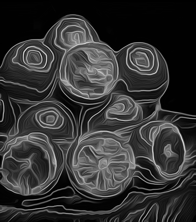 | Generate Elevation Map The first bit of information our lighting model needs is an elevation map, literally an image that indicates how high a point is from some “ground zero.” Not only does this give our model high and low points, but slopes from one to another elevation. Here, lighter values indicate higher elevations with zero intensity representing the minimum, “ground zero” baseline elevation. We construct our height map from two sources, the image of stroke edges from which we generated our diffusion tensor field, at position 5 from the end of the image list, and the smoothed “bristles” over-color image we generated in the previous step, at position 2 from the end of the image list. We make a luminance only version of the bristles and also scale it down by 70% with respect to the stroke edges. The final elevation map is the sum of these two sources, normalized to the range of zero to one. This image represents the height of our paint from the surface of the ground. Ridges made by fingers or brushes plowing through paint are generally higher (lighter) than the bristles. |
-gradient. \
-append[-2,-1] c \
=GenerateDirectionField-append[-2,-1] c \
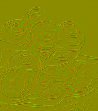 | Generate Direction Field The gradient command measures the change of intensity along principle axes, width (x), height (y) and depth (z); these approximate the partial derivatives of the surface height along each of the principle directions. For our purposes, we only need the width and height axes, the command's default output. It delivers two single channel datasets to the image list, the penultimate measuring rates of change along the width axis, the last measuring rates of change along th height axis. We append these single channel datasets along the spectral access to make a single object, the direction field. Each pixel in this field represents a vector expressing the steepness and direction of slope or gradient “observed” at the corresponding pixel in the elevation map. For our purposes, these are the slopes which incident light rays reflect from. |
'({cos(-135*pi/180)}'^'{sin(-135*pi/180)})' \
-resize. [-2],[-2],[-1],[-1],1 \
+mul[-2,-1] \
-compose_channels. add \
-cut. '{ia}','{iM}' \
-normalize. 0,1 \
-resize. [-2],[-2],[-1],[-1],1 \
+mul[-2,-1] \
-compose_channels. add \
-cut. '{ia}','{iM}' \
-normalize. 0,1 \
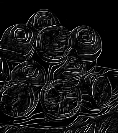 | Shadow Dot Product Up to now, we have been making remarks on surface lighting, which also includes shadowing as well. It should not come as too big a surprise to readers that shadows arise from very much the same mechanism: dot products on direction fields. In this sense, it might help to think of shadows as “negative light.” In the left hand coordinate system common for computer graphics, the origin coincides with the upper left hand corner. The positive x axis points to the right, the positive y axis points down and positive angular rotations are clockwise. In this example, we have chosen that incoming light streams in at -135°(225°) Our first dot product, then is with a unit vector oriented at -135° dotted with each vector in the direction field. We form this dot product in three phases: 1. Forming a single pixel image containing the vector components of the “shadow ray.” 2. Resizing this image to match the dimensions of the direction field, forming a constant “unit vector field.” 3. Multiplying the direction and unit vector fields, then adding the channel elements together, forming pixel-wise dot products. The lightest values coincides with slopes at right angles to the “shadow ray” The shadow dot product, depicted on the left, is initially a negative image of the shadows. We perform a -cut to isolate the range of shadow values and normalize this range to the interval [0, … 1]. |
-to_rgb. \
-mul. [-9] \
-oneminus. \
-normalize. 0,255 \
-mul. [-9] \
-oneminus. \
-normalize. 0,255 \
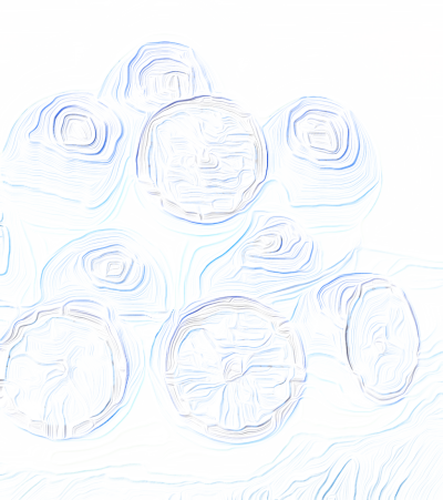 | Shadow Multiplier It is an old painterly trick to make shadows with complementary color; and that is the case here. Our ultimate aim is to make an image we can multiply with the emulated paint image. This entails multiplying our shadow dot product with the original image to pick up the color of the shadow regions, but in the direct sense. The multiplication complete, we then make a negative of the product, coloring the shadows in the complementary sense and setting the values so that shadows are dark instead of light. |
-blend[-5,-4] add \
-blend[-4,-1] multiply,0.6 \
-blend[-4,-1] multiply,0.6 \
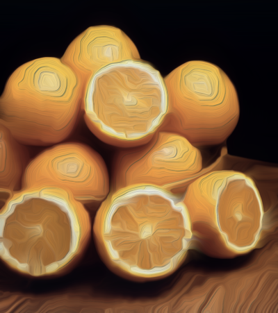 | Composite Shadows In these last three steps, we repeatedly form dot products for highlights and specular glints, then blend them with the color image. The image on the right is the initial set of blends: the over- and -under colors, then the shadow dot product. This gives an credible, but incomplete sense of a finger painting. In the next step, we composite in highlights and specular components. |
-fill_color. '{cos(45*pi/180)}','{sin(45*pi/180)}' \
+mul[-2,-1] \
-compose_channels. add \
-cut. '{ia}','{iM}' \
-normalize. 0,1 \
-to_rgb. \
+mul[-8,-1] \
-normalize. 0,255 \
-blend[-5,-1] screen,1 \
+mul[-2,-1] \
-compose_channels. add \
-cut. '{ia}','{iM}' \
-normalize. 0,1 \
-to_rgb. \
+mul[-8,-1] \
-normalize. 0,255 \
-blend[-5,-1] screen,1 \
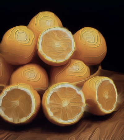 | Composite Highlights The process of generating highlights is procedurally the same as shadows; we choose a “light ray” direction of 45°, the exact opposite direction of the shadow ray, and we do not make a negative of the product. |
-normalize. -2,0 \
-exp. \
-normalize. 0,255 \
-blend[-4,-1] screen,0.5 \
-rm[^-3] \
-exp. \
-normalize. 0,255 \
-blend[-4,-1] screen,0.5 \
-rm[^-3] \
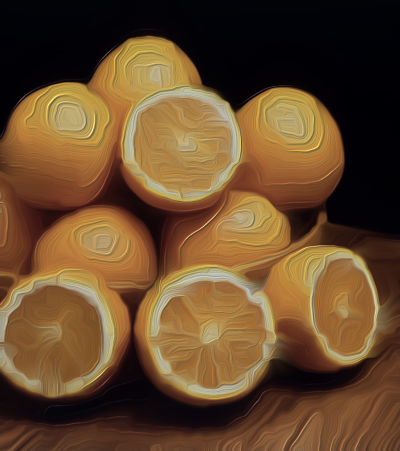 | Composite Specular The specular glints are just the uncolored highlight dot product reused, distorted exponentially. We normalize the highlight dot product from a large negative value to zero, then raise Euler's Number, e, by elements of this field, obtaining scalars that cluster more closely to zero as we drive the lower normalization boundary more negative. In a rougher parlance, “more negative” means “wetter, shinier” speculars. |
Code in this tutorial has been implemented as a Gimp-GMIC Filter. See The Fingerpaint Filter in the Artistic section.


 Home
Home Download
 News
News Mastodon
 Bluesky
 X
X Summary - 17 Years
 Summary - 16 Years
 Summary - 15 Years
 Summary - 13 Years
 Summary - 11 Years
 Summary - 10 Years
 Resources
 Technical Reference
 Scripting Tutorial
 Video Tutorials
 Wiki Pages
 Image Gallery
 Color Presets
 Using libgmic
 G'MIC Online
 Community
 Discussion Forum (Pixls.us)
 GimpChat
 IRC
IRC Report Issue